Spin-Rotation Coupling
February 14, 2020 10:39 amThe effect of spin–rotation coupling, refereed to as Sagnac–Mashhoon phase, has been measured by our group for the first time with neutrons in a interferometric experiment 1. The basis of the Sagnac effect lies in the influence of rotation on the phase of light passing through an interferometer. An inertial observer in the frame of an rotating interferometer of frequency , will observe that the wave vector of any radiation is . Thus a phase shift proportional to the scalar product of rotation frequency and area of the interferometer occurs. This phase shift can be extended to include the intrinsic spin of a quantum mechanical particle when replacing the orbital angular momentum, denoted as , by the total angular momentum . This results in an additional phase shift due to the spin-rotation coupling. In a paper published in 1998 2 Iranian born physicist Bahram Mashhoon proposed a neutron interferometric test of the Sagnac-Mashhoon phase, where a longitudinal polarized beam passes through a slowly rotating spin flipper placed in one arm, is proposed.
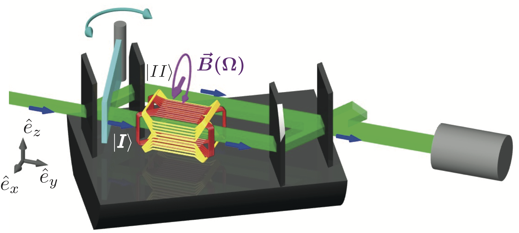
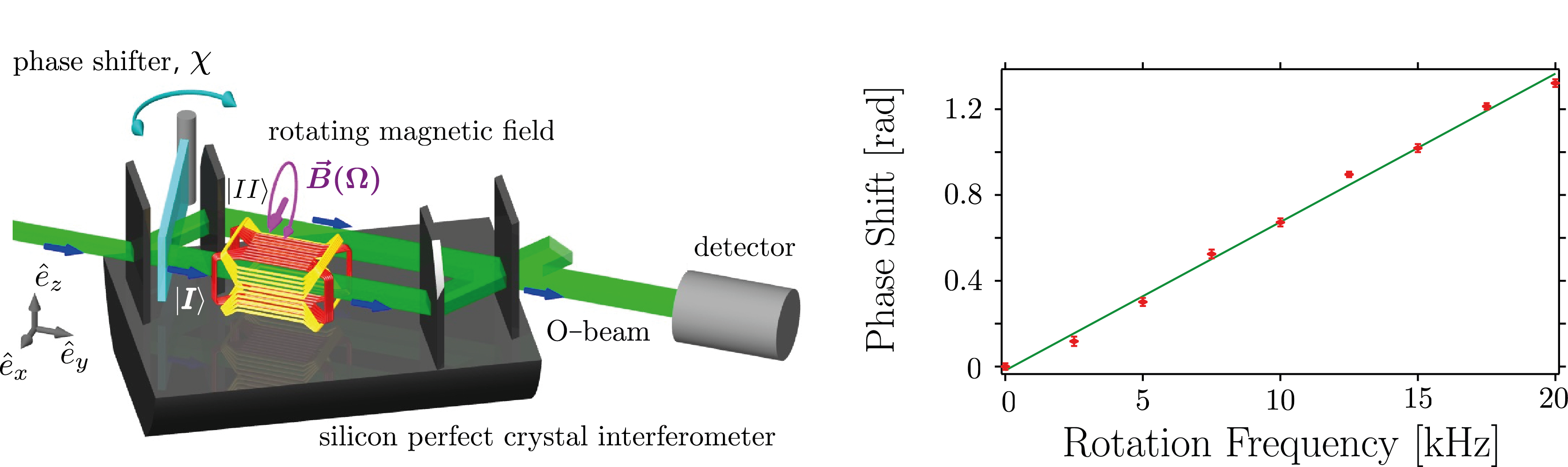
The actual neutron interferometric setup is shown below (left). Polarized neutrons initially propagating in +y− direction are split into two arms of an interferometer of which one contains a rotating spin flipper whose angular velocity vector is parallel to the initial neutron spin. In this path the neutron’s spin is manipulated by the rotating magnetic field to undergo a cyclic path. As the orientations before and after the manipulation are the same, only a phase difference between the sunbeams is induced. The first proposals of the experiment suggested the use of a mechanically rotating coil, analogous to the HWP in the optical interferometer scheme, but it was pointed out later that this situation is physically equivalent to a static quadrate recoil producing a rotating magnetic field . The accumulated phase difference results in a shift of the observed interference fringes which turns out to depend solely on the frequency of the rotation of the magnetic field, as can be seen in the final results below on the right side.
To describe the interaction of the spin of a free neutron in a magnetic field with angular velocity the Pauli–Schrödinger equation has to be solved for a particle propagating in − direction in a uniformly rotating magnetic field given by which gives (see here for details of the derivation). The Pauli equation in a rotating magnetic field for plane waves is analytically solvable and in this particular case given by , where generates the rotation of the initial spin state , which cab be expressed as . The square of the magnitude of the rotation vector is given by a Pythagorean equation , where we used the definition of the Larmor frequency . The solution from above contains the coupling term and describes the evolution of the spin states for both the rotating and the static field (). Instead of a flip it is better to choose a multiple of in which case the dynamical part becomes disengaged from the spinor function and the phase shift can be attributed purely to a geometric phase.
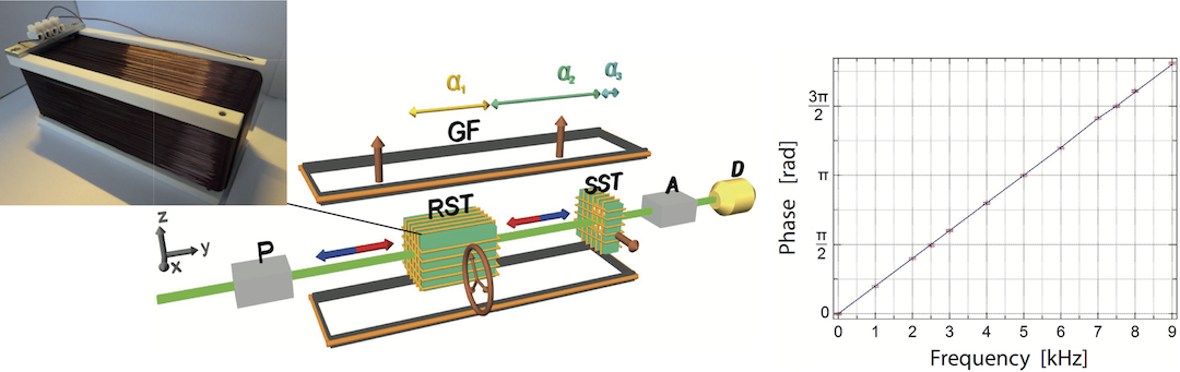
Before the actual interferometric experiment a polarimetric test of the spin-rotation coupling was carried out first 3 . The polarimeter setup, together with the results are depicted above. The uniformly rotating magnetic field, given by , is generated by the rotating field generator (RFG), the central neutron optical element of this experiment. The RFG can be seen in the photo above (left). If we prepare the incident beam in our polarimetric setup, which is depicted above (left), to be the effect of the spin–rotation coupling can be seen when we c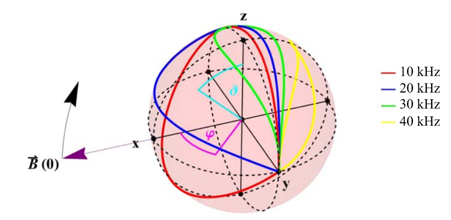 hoose to represent the initial state as a superposition of and states. The outcome of the spinor function in this set-up after a time and a rotation , which is illustrated aside for different frequencies with initial state . Note that the area of the evolution path traced out on the Bloch sphere gets smaller for higher frequencies. This changes an initial superposition state to . The corresponding change in the polarization vector (from ) is . For higher precision and feasibility it is more convenient to keep constant and scan a relative phase, just like in an interferometer experiment where phase shifter scans are performed. The observed phase shift is plotted above (right) as a function of the frequency. A linear behaviour is clearly seen, as theoretically expected. All results are within the error bounds of the expected values predicted by the Pauli–Schrödinger equation. The final average contrast of 95.23(84)% confirms the high reliability of our measurement.
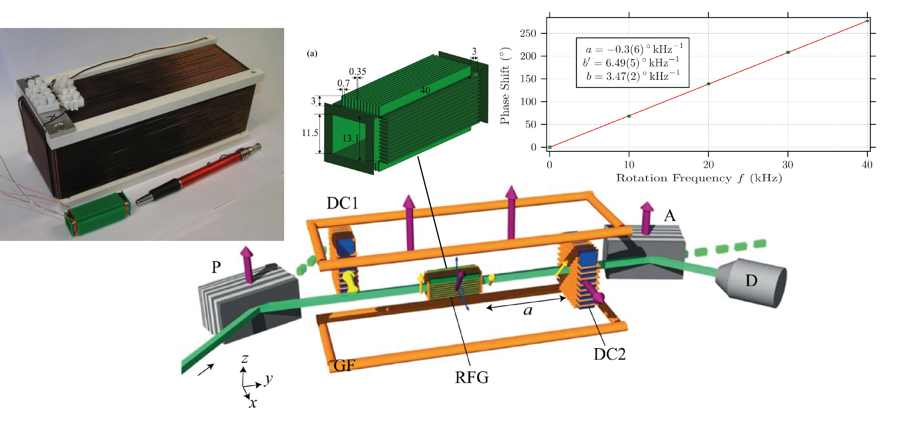
In a next step, for preparation of the actual neutron interferometric experiment, the RFG needs to be miniaturized by almost one order of magnitude, to fit in the neutron interferometer. The coil design was chosen such that no material (wire or coil mount) is in the beam path, which is also required for the actual neutron optical experiment. The coil mount was constructed and 3D-printed. With a length of approximately 50 mm, the coil is short enough tofit in various silicon perfect crystal interferometers. The results of the re-implementation of the first polarimetric experiment 3 using the newly developed RFG suited for interferometric application, are reported in 4 and can be seen above. Before the experiment an extremely expensive field simulations show a sufficient field homogeneity to be applied in the experiment. See here for details of the field simulation. The presented rotatingfield generator is suited for the proposed experiment by Mashhoon et al., 2 investigating spin-rotation coupling in neutron interferometry, that will be carried out in not too distant future.
1. A. Danner, B. Demirel, W. Kersten, H. Lemmel, R. Wagner, S. Sponar, and Y. Hasegawa, npj Quantum Information 6,23 (2020) ↩
2. B. Mashhoon, R. Neutze, M. Hannah, and G. E. Stedman, Phys. Lett. A 249, 161 (1998). ↩
3. B. Demirel, S. Sponar, and Y. Hasegawa, New. J. of Phys. A 17, 023065 (2015). ↩
4. A. Danner, B. Demirel, S. Sponar, and Y. Hasegawa, J. Phys. Commun. 3, 035001 (2019). ↩