CANISIUS – ATI, Vienna
September 22, 2015 9:27 amThe CANISIUS Instrument at Atominstitut (TU Wien)
The CANISIUS (Coherent Averaging Neutron Instrument for Spin-echo Interferometry and fUnda-mental Science) instrument is a highly versatile, state-of-the-art instrument operating at the white beamline of the 250 kW TRIGA Mark II research reactor at the TU Wien Atominstitut in Vienna, Austria. It is custom-built to support a dual mission: pushing boundaries in advanced materials science via SESANS, while serving as a fundamental physics interferometer to probe quantum mechanics.
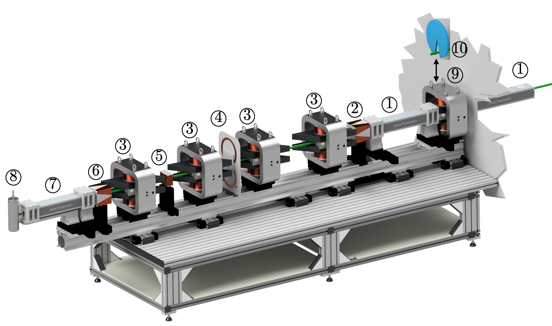
The render of the CANISIUS instrument configured for white beam SESANS (Spin-Echo Small Angle Neutron Scattering) is shown below. The beam propagates from right to left. First, the beam is polarized by double reflection from two single substrate m = 4 polarizing supermirrors (1). Next, the polarization is adiabatically rotated by 90 by a v-coil (2). The beam then passes through a pair of adiabatic RF flippers with parallelogram shaped poleshoes, which act as the first beam splitter and mirror (3). A field stepper is positioned between the first and second pairs of RF flippers, to facilitate a fast non-adiabatic field transition from arm 1 to arm 2 (4). The samples of various types may be inserted right before the field stepper. The second arm of RF flippers serves effectively as a mirror and beam splitter to recombine the split beams. Between the last two RF flippers, the beam is passed through a precession coil (5), which manipulates the spin phase to measure the spin echo curve. Finally, before the spin is selected by the last polarizing supermirror (7), the neutrons pass through a final v-coil facilitating another adiabatic 90 degree rotation (6). Neutrons passing the polarizing supermirror are detected by a high-efficiency 3He counting tube. In addition to the usual continuous mode of operation, the CANISIUS instrument can also be operated in ToF mode. For this purpose, two chopper device are available: a conventional mechanical chopper (10) as well as a spin-chopper system (9), consisting of an RF flipper in combination with the pre-polarizer, that is, the very first supermirrors (1). The length of the instrument, given by the distance between chopper (9 and 10) and detector (8), is 3 m.
Architectural and Technical Specifications

The operational architecture of CANISIUS comprises several distinct components engineered to optimize neutron utilization from a medium-flux source:
- Broad-Band Polarization System: The continuous white beam from the TRIGA reactor is initially polarized using double reflection via a pair of high-performance m=4 single flat substrate supermirrors. This setup delivers exceptional polarization efficiency across a wide band of neutron wavelengths.
- Advanced Time-of-Flight (ToF) Configurations: To extract maximum data from a continuous reactor source, CANISIUS can switch between a continuous broad-band beam and two distinct Time-of-Flight (ToF) modes:
- Mechanical Chopper ToF: Uses a standard mechanical chopper disk to slice the beam into wavelength-dependent packets.
- Innovative Spin Chopping ToF: Leverages a fast, pulsed radio-frequency (RF) broad-band spin flipper positioned cleanly between the two supermirrors. This configuration manipulates neutron spins directly to pulse the beam without moving parts, eliminating the mechanical wear, geometric limitations, and speed constraints of physical choppers.
- Resonant Spin Echo Operation: Instead of using massive, heavy electromagnets with tilted physical faces, CANISIUS implements Neutron Resonant Spin Echo (NRSE). It employs high-frequency radio-frequency (RF) spin flippers to simulate the boundary conditions of tilted fields. The functional principle of SESANS (Spin-Echo Small Angle Neutron Scattering) without RF Flipper (just tilted magnetic regions): A polarized neutron beam passes through a magnetic field region with inclined boundaries. The magnetic field triggers Larmor precession of the neutron spin, where the total accumulated precession angle depends strictly on the path length traveled through the field. After passing through the sample, the neutrons enter a second magnetic field region featuring an identical but reversed magnetic orientation (or utilize a π-flipper configuration). If a neutron passes through the sample without scattering, the second field perfectly unwinds the precession accumulated in the first field, recovering 100% of the initial polarization—a phenomenon known as the spin echo. However, if a neutron scatters by a small angle θ inside the sample, its path through the second field changes relative to the first. This path difference prevents a perfect unwind, causing a measurable drop in the final polarization.

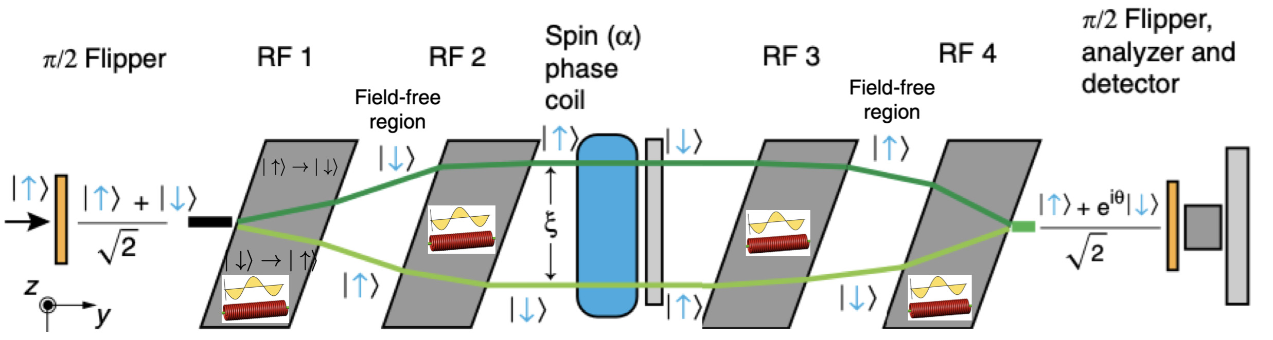
Actual implementation using RF Flippers: Instead go a long static magnetic field a RF flipper is used; due to the different total energies of the orthogonal spin states zero field precession occurs. Since the spins are flipped inside the Rf coils a second RF Flipper is needed to stop the separation of the spin states, which is depicted below.
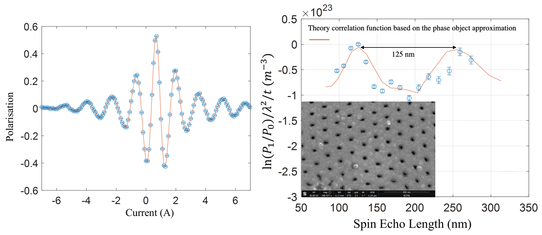
In both cases the measured polarization is related to the real-space structure via the relation: , where is the total scattering cross-section, is the real-space correlation function, and represents the *spin-echo length*. The variable functions as a virtual ruler in real space. It is scaled dynamically by adjusting the magnetic field strength or the neutron wavelength (), completely bypassing the need to physically move detector components. An object the size of the spin-echo length is the smallest object capable of causing a measurable change in polarization. Se below for a typical spin-echo curve (left). The spin echo length of CANISIUS was calibrated using a nanoporous alumina membrane, where the pores used have a diameter of 40 nm, with a pitch of 125nm and a thickness of 50 microns (right) 1 .
Structured Wavefunctions and Quantum Topology:
Constructing structured wavefunctions by coherent averaging is the main purpose of the CANISIUS instrument. This is done primarily to produce neutron wavefunctions that have non zero Orbital Angular Momentum (OAM) and to investigate the properties of these states. Put simply, coherent averaging is an interferometric technique that takes an input wavefunction with simple structure (i.e., Gaussian) and splits it multiple identical copies, called partial wavefunctions. These partial wavefunctions can then be independently translated and phase shifted in real or reciprocal space to produce a composite wavefunction (i.e., the coherent sum of all partial wavefunctions) that exhibits the desired structure. This technique is particularly well suited for producing neutron OAM. The structured wave is produced by running the instrument in a new mode, where the first and second arms have different poleshoe angles. As a result, the two spin states retain some transverse separation after passing through the spin echo interferometer. The concept is illustrated below (left), together with a simulation of the OAM distribution function for various residual spin echo lengths .

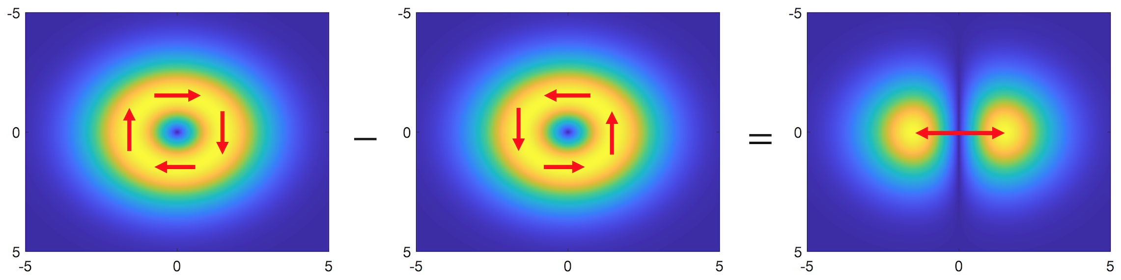
For small – with respect to the coherence length – the output wavefunction can almost entirely be described by the and modes, i.e., a right and left twisting mode, somewhat analogous to linear polarization. The concept of a “linear” OAM state is illustrated below, where a left rotating state is subtracted from a right rotating state to produce a linearly polarized (sine oscillation) state.