Field Simulations
March 7, 2019 5:17 pmThe geometry finally used as rotatingfield generator is shown in the picture below. Its winding is similar to a static spin rotator stretched in longitudinal length. The only difference are the free windows for the neutron beam, which is reqired for a neutron interferometer experiment.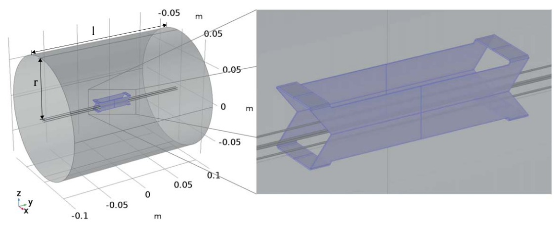
The simulatedfield of the modified Helmholtz coil has pronounced inhomogeneities infield direction andamplitude over the beam cross-section(not shown). The minimised heigth of the solenoids, necessary to reducethe diameters for an interferometer experiment, reduces thefield homogeneity. Thefield transition on thecentre axis is about 20 mm long.
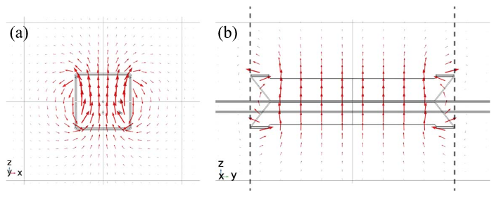
The simulated magneticfield of the rotatingfield generator in the centre x-z-plane is depicted infigure4(a)and the simulatedfield in the centre y−z-plane is depicted in (b). Bothfields are homogeneous infielddirection and magnitude near the centre and more diverged close to the winding. Thefield along the centre axis,presented infigure5(a), is purely oriented inz-direction with a maximum amplitude of more than 10.5 G whichis of the order of the amplitude specified as necessary for spin manipulations of 10 G. In front and behind thecoil, an opposingfield of 0.5 G emerges. The transition length, defined as distance between minimum andmaximum, can be estimated to about 20 mm. For afirst assessment of the suddenness caused by this field transition length, the length must be compared with the Larmor precession length of the order of 100 mm intypical guidefield strengths and for the typically used thermal neutrons with Å. The simulated transitionlengths are less than one order of magnitude shorter and therefore not sufficiently short for a sudden field transition. However, in fact it turned out that thefield transition of the rotatingfield generator was sufficientlyshort for inducing the linear phase shift in the experiment expected from the calculation.
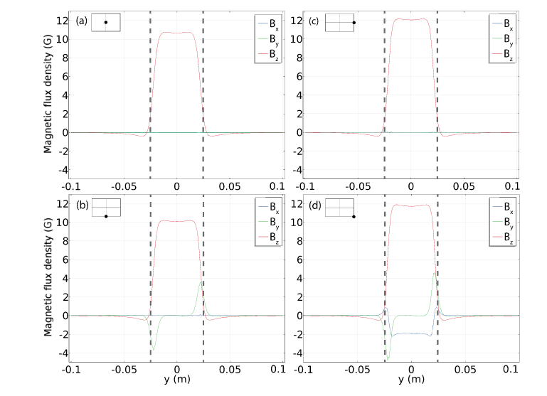
On beam paths other than the centre axis, other field directions (x and y) are present. For the three extreme lower,right and lower right transitions of the beam at positions indicated in the plots above this can be clearly seen.