Phase Shifters
October 2, 2016 5:07 pmBy inserting a phase-shifter plate in one of the two beam paths in the neutron interferometer (either I or II) the phase relation between the two sub-beams can be systematically varied. Here, we discuss several aspects of phase shifters in various configurations.
Contents:
Phase shifter basics
Sample geometries
Dual phase shifters
Dispersion cancelation
Phase shifts of perfect crystal samples
Phase shifter basics
Thermal neutrons passing a slab of material undergo a phase shift and a spatial displacement . Both effects are coupled in the most
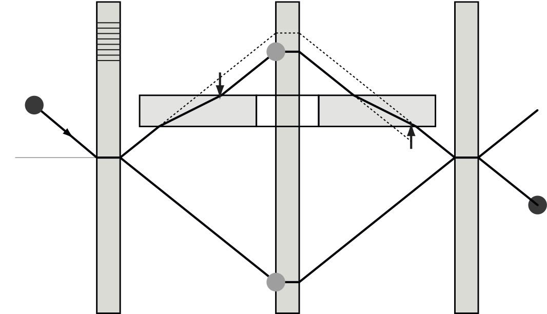
 situations, although a decoupling is possible, see ‘dispersion cancelation‘.The phase shift depends on the change of the wave vector component perpendicular to the phase shifter surface, and on the phase shifter thickness, which is illustrated below. The wave vector is denoted by outside and inside the phase shifter respectively. and This relation can be used to determine the neutron coherent scattering length which is a key parameter for most neutron scattering experiments. denotes the atom density and the sample thickness. For the spatial displacement we consider as the central component of a wave packet. The group velocity equals . Inside the phase shifter the wave length increases, the normal wave vector decreases and the velocity as well. When the wave packet leaves the phase shifter at point an unperturbed wave packet would already be at point , since . It follows that . Phase shift and spatial displacement are related by , which is reported in 1.
Sample geometries
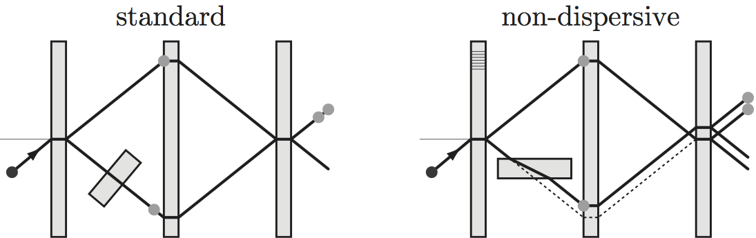
In the standard alignment the sample surface is perpendicular to the beam. However, there is an interesting alternative, the so-called non-dispersive geometry, which is illutrated below on the right side. To understand the benefit we have to look closely at the distribution inside the interferometer. The beam is Bragg diffracted at the interferometer blades. Bragg’s law in vector notation then reads
 where denotes the reciprocal lattice vector perpendicular to the lattice planes. Bragg’s law is fulfilled for any wave component parallel to the lattice planes but only for a single component perpendicular to the lattice planes. The meaning of ‘single’ is given precisely by the dynamical diffraction theory which yields . In contrast, is given by the beam preparation in front of the interferometer and is usually in the order of a few percent. By aligning the sample perpendicular to , i.e parallel to the lattice planes, only the well defined enters into the phase shift. The wave length of the incident beam is effectively replaced by (twice) the lattice constant of the crystal 2. Methods for the precise sample alignment are given in 3 and 1.
 In addition to the phase shift both sample geometries create a spatial displacement of the wave packet.This reduces, in principle, the wave packet overlap at the interferometer exit and thus the visibility of the interference fringes. In the standard geometry, the displacement is parallel to the beam, equivalent to a time lag. In the non-dispersive geometry, the displacement is perpendicular to the lattice planes, equivalent to a de-focusing of the interferometer loop. However, for thermal neutrons this problem is negligible, since the displacement is much smaller than the coherence length of the beam.
Dual phase shifters
If two samples of the same kind are inserted simultaneously in two different sections of the interferometer one can create various
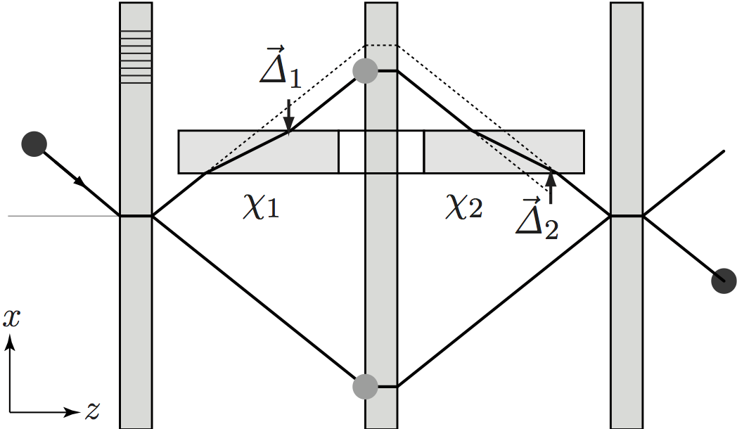 combinations of doubling and canceling phase shifts, spatial displacements, dispersion etc. 1. Of special interest is the setup consisting of two samples in non-dispersive geometry, one before and one after the mirror blade. The lateral displacement of the first sample is reversed by the second, and both beam paths of the interferometer reach the third interferometer blade at the same point. In addition, the velocities parallel to the lattice planes are not changed throughout the setup, and thus the wave packets from both beam paths reach the third blade simultaneously. The interferometer is always fully focused however thick the samples become. Still the phase shift of both samples sums up and does not vanish. Why are phase shift and spatial displacement de-coupled in this setup? It can be explained by ‘odd-order dispersion cancelation’.
Dispersion cancelation
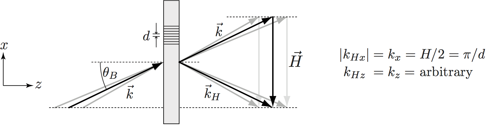
To understand the non-dispersive dual phase shifter we need several ingredients. i) The phase shift created by a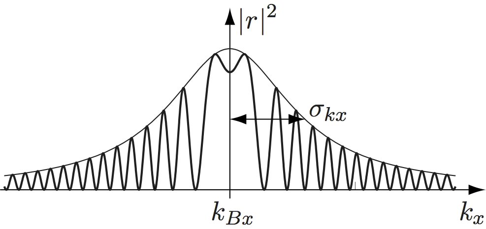 sample depends on , i.e. the wave length. Consequently, each component of a wave packet obtains a slightly different phase shift. In the non-dispersive sample geometry the distribution equals the distribution created by Bragg diffraction on the interferometer crystal. It is given by the Laue reflection factor . A typical distribution is depicted below. The central wave component is given by Bragg’s law. For thermal neutrons the distribution is very narrow, .
ii) A general concept of wave optics are the so-called dispersion orders. We denote the phase shift of a certain wave component by and make a series expansion. It can be shown that the individual expansion orders have certain physical meanings. The zero order is the overall phase shift. The first order equals the wave packet displacement. It turns out that , which we have obtained before. The second order creates the wave packet spread. Higher orders create additional deformations of the wave packet envelope.
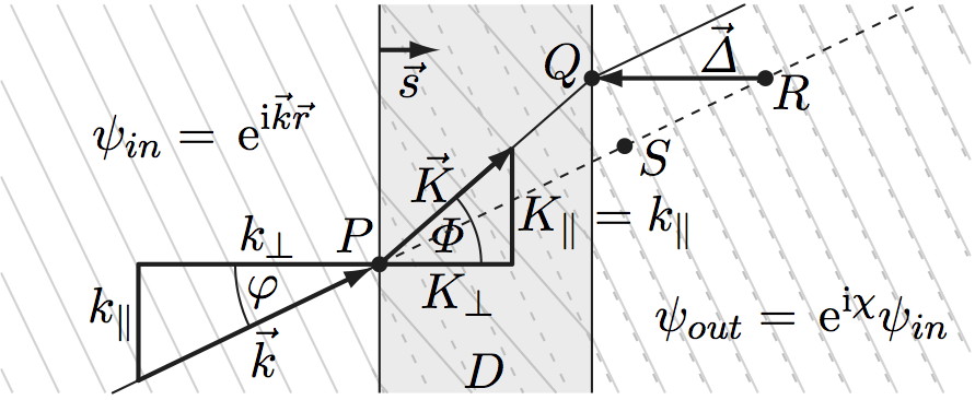
iii) Laue reflection is non-specular for near-Bragg wave components. The reflected wave vector is obtained by adding the 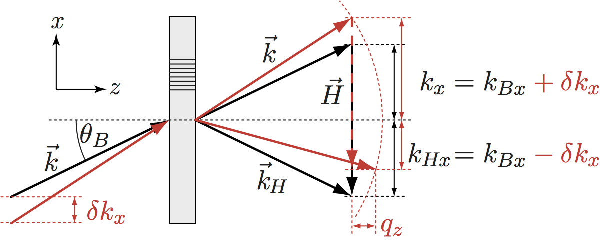 reciprocal lattice vector to the incident wave vector , see figure below. If the Bragg condition is not exactly fulfilled because the incident is e.g. slightly larger than then the reflected is slightly smaller than by the same amount. In other words, Laue reflection turns the faster components into slower ones <0 and vice versa. (To obey energy conservation, an additional vector perpendicular to the crystal surface is added to near-Bragg components. However, this does not affect .)
Now we determine the overall phase shift for the non-dispersive dual phase shifter. A particular wave component collects the phase shift at the first phase shifter transit. During the following Laue reflection is turned into . The second phase shifter transit contributes and the total phase shift reads . Because of the sign change all odd dispersion orders of the total phase shift cancel while the even orders double. There is no spatial displacement but double the phase shift. Since all higher orders can be neglected for thermal neutrons (the second order is by smaller than the zero order) the phase shift is truly non-dispersive for all practical purposes. Such a feature is otherwise known only from geometrical and topological phases.
Phase shifts of perfect crystal samples
If a perfect crystal is used as a phase shifter and is measured close to a Bragg condition, the phase shift deviates from the standard phase shift. One can also state that the index of refraction changes close to Bragg conditions. In an extreme case, if the sample material and the Bragg planes are chosen similar to those of the interferometer crystal, the sample can reflect the beam intensity out of the interferometer or displace the beam macroscopically and defocus the interferometer 4. Otherwise the sample crystal and the interferometer crystal are in dispersive configuration to each other, meaning that only a tiny fraction of the beam meets both Bragg conditions exactly. Then no intensity loss is observed but only phase changes and reduction of contrast.
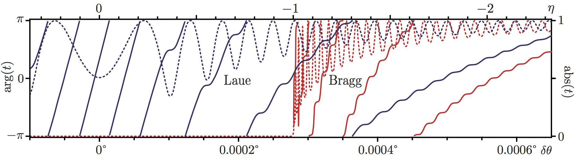
The text book formulas for the transmitted and reflected beam of a Bragg crystal (two-beam case of dynamical diffraction) are valid only in the vicinity of the 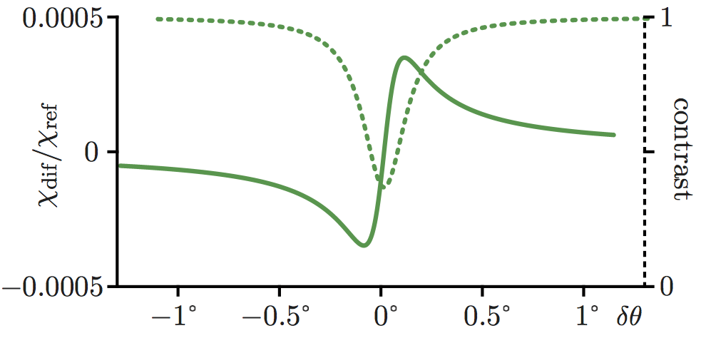 Bragg condition. This is sufficient for most applications since the reflected intensity vanishes very quickly for increasing deviations from the Bragg condition. However, the phase of the transmitted beam is influenced for much larger Bragg deviations 5. Then the following formulas are appropriate. They are valid for arbitrarily large Bragg deviations for the symmetric Laue case (the solutions for arbitrary Bragg and Laue cases can be found in 6). We get , , , , , , and . The difference to the text book formulas is, that the defined here contains the vector component inside the crystal rather than the incident component (see here for textbook version). Argument and modulus of the transmission factor are shown above.
In a true measurement the beam divergence is typically in the order of °. This means that the phase shift is averaged over a wide range in the figure above. The contrast drops since different parts of the beam are phase shifted by a different amount. One typically expects the following curves, calculated for a 18mm thick silicon crystal. The relative phase change is in the order of . Since mm of silicon create a phase shift of about times °, the relative phase change is in the order of ° and can be very well measured.
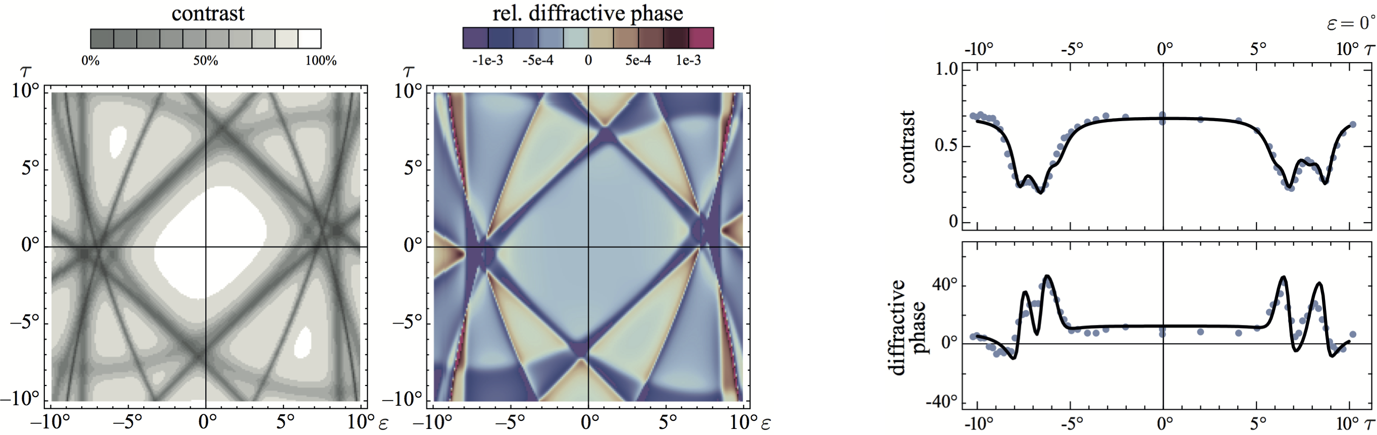
By rotating and tilting the sample (by and respectively) one can access a whole grid of various Bragg conditions, as calculated in the plots above (left). Finally a comparison between the calculated and measured data is given above (right).
1. H. Lemmel and A. G. Wagh Phys. Rev. A. 82, 033626 (2010).↩
2. D. Petrascheck, Phys. Rev. B. 35, 6549 (1987).↩
3. A. Ioffe and D. L. Jacobson and M. Arif and M. Vrana and S. A. Werner and P. Fischer and G. L. Greene and F. Mezei, Phys. Rev. A 58, 1475 (1998).↩
4. J. Springer and M. Zawisky and H. Lemmel and M. Suda, Acta Crystallographica A 66, 17 (2010).↩