Basic Concept & History
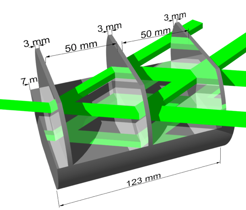
May 19, 2017 10:12 amIn a neutron interferometer 1 a monochromatic beam of massive particles is split by amplitude division (Mach–Zehnder type) via Bragg reflection, in triple Laue (LLL) configuration. At the first plate of a silicon perfect crystal interferometer, which is cut from a single rod, the incoming neutron beam is split into two sub-beams. The coherently superposed sub-beams (partial wave functions) then passes through different regions of space before they are recombined at the third plate of the interferometer, where the interfere constructively and destructively.
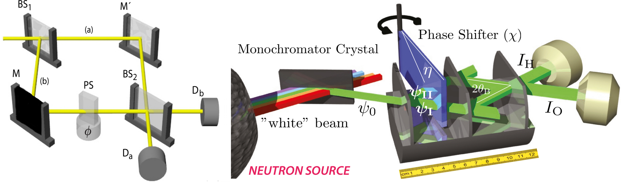 Behind the first plate, acting as a beam splitter (due to Laue reflection – see below), the neutron’s wave function is found in a coherent superposition state of the transmitted and a reflected sub-beams, which can be written in terms of , where and are the transmission and reflection amplitudes ( for neglect able absorption since silicon has essentially zero absorption for thermal neutrons) with . Next an additional slab (phase flag), inducing an adjustable
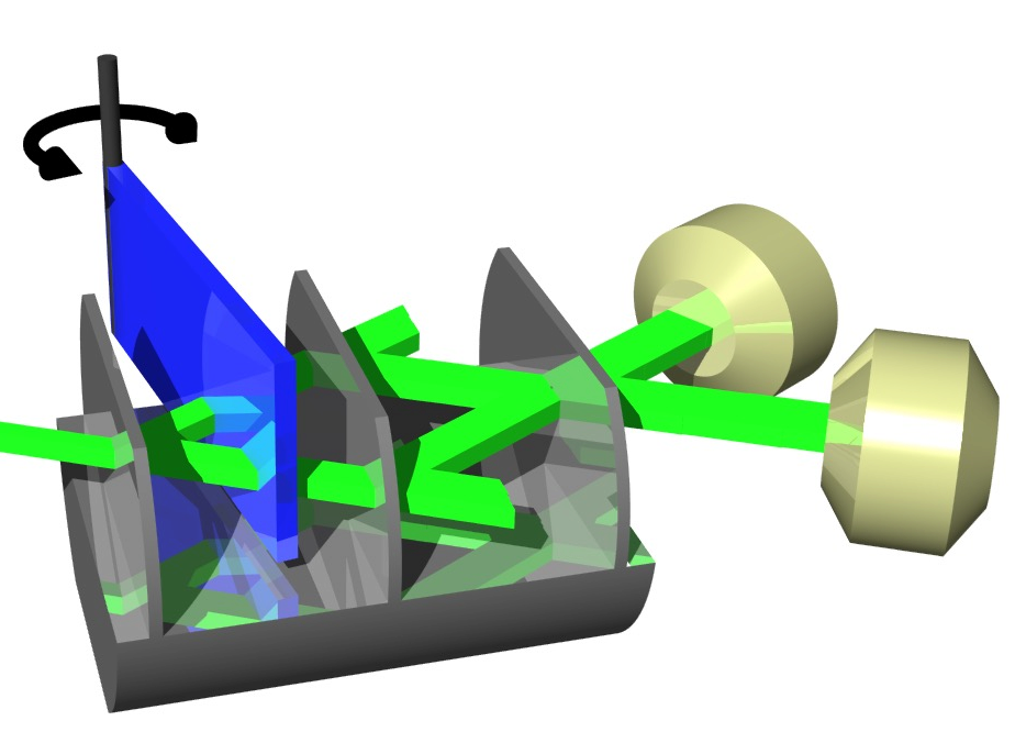
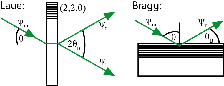 phase shift is inserted, which yields , where , with the thickness of the phase shifter plate , the neutron wavelength , the coherent scattering length and the particle density in the phase shifter plate. For instance, 0.15 mm of aluminium at 2 Å wavelength cause a phase shift of rad. This can be rewritten as , with . As it is only the relative phase shift of the partial beams that counts for interferometry, it has become a widely used method to rotate a slab of matter that extends across both sub beams about an axis perpendicular to the interferometer. The thickness of the slab is therefore changed differently for the two partial beams, depending on the angle , as depicted above. Thus the phase difference is determined by the path difference, which yields , where
 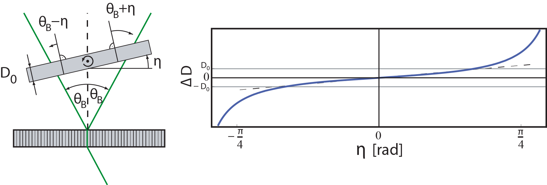 is the Bragg angle and the rotation angle of the phase shifter slab. As seen in on the right side the function is almost linear for small . Thus an interferogram recorded versus remains sinusoid essentially. By rotating the plate, can be varied systematically. Leaving the interferometer at the third plate, where the sub-beams are recombines, the neutron’s final wave function on forward direction (O-direction) is given by . Thus the intensity in the O-detector is given by , with . In similar manner we get in deviated (diffracted) direction (H-beam) , with . From particle conservation it follows immediately that . This behavior of the two intensities and is illustrated in the animation below (for dimensions of the interferometer click here).
A brief historical digression
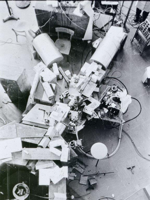
click on photo for a larger image
In 1964, when advances in semiconductor technology had allowed the production of large monolithic perfect crystal silicon ingots, U. Bonse and M. Hart invented a single-crystal interferometer for X-rays based on the effects of dynamical diffraction in perfect crystals. This type of interferometer was then applied to neutrons, resulting in the first interference fringes sighted in 1974 by Rauch, Treimer and Bonse at the rather small (250 kW) TRIGA reactor at the Atominstitut – TU Wien, Vienna, Austria (or rather Atominstitut der österreichischen Universitäten, as it was called back in that days). A picture of the first obtained interferogram is given below on the right hand side. 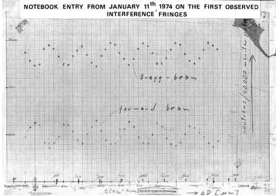 The obtained interference demonstrates in impressive manner the wave-like nature of neutrons. This sensational find later continued to bring Prof. Rauch and the Atominstitute world fame in the entire scientific community and made Vienna the world’s the center of neutron interferometry. Over the years numerous remarkable experiments on the fundamentals of quantum mechanics, have been carried out using neutron interferometry. Just to mention a few, there is the verification of the 4-spinor symmetry, followed by investigations of the influence of gravitation of the earth on the neutron’s wavefunction, and experiments on spin superposition, as well as topological phases. A detailed summary is given in the book Neutron Interferometry: Lessons in Experimental Quantum Mechanics, by Helmut Rauch and Samuel A. Werner 2, which includes more than 40 neutron interferometry experiments along with their theoretical motivations and explanations.
1. H. Rauch, W. Treimer, and U. Bonse, Phys. Lett. 47A, 369-371 (1974). ↩
2. H. Rauch and S.A. Werner, Neutron Interferometry, Clarendon Press Oxford (2000). ↩